I have been doing a lot of reading about fencing design. I checked out about a dozen books on fencing from the library, but found them all to be inadequate in their treatment of non-decorative, practical fencing for livestock. So, the “Interweb” (as Kirk likes to call it) helped me a lot. These nice folks at Gateway Farm Alpacas have the best advice, by far, that I have found for installing field fencing, which is the type I chose to use. I also found good help on the websites of fencing manufacturers, with installation instructions for their own products.
It occurs to me that perhaps the most important component of any fence under tension is the end-bracing. Granted, I’m not doing a high-tensile fence, but field fencing still takes plenty of stretching to make it strong and non-saggy. I have come to realize that there isn’t a lot of good advice out there about designing end-braces, or the “why” behind the design. And as I drive through our county, I see many more examples of failed end-braces than successful ones. So, after a lot of reading, studying other people’s mistakes, and thinking, here is what I’ve concluded on the end-brace debate. Now, I’m no mechanical or civil engineer, I’m of the electrical bent; but I did have to take a few ME and CE courses in college, enough that I grasp the basics of statics & dynamics, and physics. So, here is my stab at explaining what happens to end-braces, why they are prone to failure, and how to best ensure their strength and longevity.
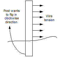
The first step is to think about what is happening to the end post on which multiple horizontal wires are pulling. The most concerning point is near the top of the post, due to torque (think of a long lever…), the force on the post is greatest here. The post, especially if you didn’t bury it really deep, is going to want to “flip” sideways out of its hole. This is because the bottom isn’t going to experience enough resistance from the soil to counteract all that force on the top of the “lever.” The soil is going to “give in” and erupt vertically, allowing the post to migrate and eventually lean, which allows the fencing to become slack at the top. This will mostly likely happen very slowly over years; though I have heard of it happening to people the instant they tensioned the fence, if they did an especially poor job of brace design! Here is a picture of what this lever action looks like:
Additionally, the post is also going to want to bend, because its tensile strength is being challenged. This part is easier to address by using very thick (usually 6″x6″) posts with no flaws, which offer greater tensile strength. So, that just leaves the leaning tendency to fix. There are many solutions people offer to address this problem. But I feel the most practical and wisest solution is the “H-brace.” The idea is to transfer most of this load to a second post, and allow that post transfer the load back to the bottom of the first post, offering a counter-force. So, first let’s focus on transferring the load to the second post:
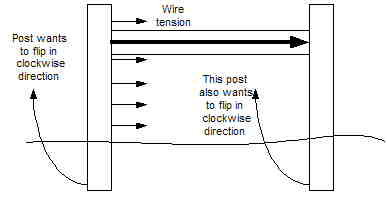
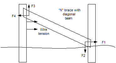
By putting a horizontal beam in between the end post and second post, it’s easy to see that much of the load on the first post will now be pushing on the top of the second post. But, this, by itself, is no help; because of course the second post is now going to want to “flip” in a clockwise direction too. What’s needed is a diagonal wire wrapped around both posts, tied back down to the bottom of the first post, and then tensioned, to transfer the load back down to the bottom end of the “lever.”
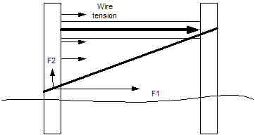
Above, you can see how the diagonal wire is going to pull on the bottom of the end post as a reaction to the cross-piece pushing on the second post. Physics 101 teaches you how to break down a diagonal force vector into is horizontal and vertical components (F1 and F2 in the diagram). You can do this mathematically using trigonometry, but here I’m just going to show it intuitively, the precise math isn’t as important as the general concept.
The goal is to create a “long” triangle as above, where the wire is pulling more in the horizontal direction (F1) than the vertical (F2). The vertical component of force (F2) is actually undesirable, because it’s going to encourage the post to pull up out of the soil, so we want that to be as small as we can manage. What we want is more F1 force, which will counteract the lever action happening at the top of the post, pulling it at the bottom to make it stay standing up straight.
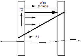
The mistake many people make is creating too narrow of an H-brace, so that their diagonal wire has a very steep angle, instead of a very flat angle. This means there is more upward (F2) force than sideways (F1) force, so over time, the end post could possibly pop out of the ground from the vertical strain. The rule of thumb I’ve read is that you want angle no bigger than 45° from the ground, and preferably less. So make your H at least twice as wide as your fence is tall, though 2.5 times as wide is better.
The reason H-braces are the most popular method is that they are the easiest and cheapest to install. Merely:
1. drill holes for, and then pound in brace pins (foot-long rebar works well) to secure the cross-beam (you can notch the posts too, but it’s extra work, and doesn’t gain much),
2. use a heavy gauge wire for the diagonal, securing it with staples top and bottom (or you can hook it over a sticking-out brace pin at the top),
3. then tension the wire by twisting a “twitch” stick in the middle of it (or use a new-fangled, store-bought tensioner device) until its firm.
One alternative method to the H-brace is an “N” shaped brace. It involves making a diagonal out of another beam, that travels from the top of the end post down to the bottom of the second post, so that as the end post wants to “flip”, it’s pushing against a diagonal brace that resists this motion. The theory is good, but I think this method is less practical because first, you have to buy an expensive, long post to make that diagonal (a 10- or 12-footer for a 4′ high fence), rather than letting inexpensive wire be the long component. And, it’s more challenging to truly secure that diagonal to the end points, so that things won’t just “scoot” around, or cause nails to pop, when forces are applied. You need to do a fancier job of notching and securing, which is often inconvenient when you are way out in a pasture without power and your whole tool box. Wire is a lot easier to secure than an angled junction between to beams, especially for laymen.
I’ve often seen examples of braces where someone put the diagonal wire in the wrong direction. This actually has zero affect long-term, because as the end post starts to lean, it’ll slacken the tension on the diagonal wire, such that it starts to do absolutely nothing. But when first built, the moment the diagonal wire is tensioned, it’s actually going to put more force on the top of the end post, causing it to want to lean more than ever! In this case, the only saving grace of the “H” is that the load is still shared between the two posts, which is better than nothing at all; but it’ll probably still fail over time.
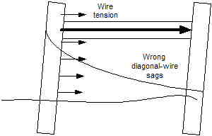
Another mistake I’ve seen is people putting diagonal wires in both directions, and then tying them together by twisting the twitch stick in the middle of both. If you feel you must do two diagonals (which makes sense on an H-brace that’s mid-run on a long fence line, or if you have a gate pulling on an end post in the opposite direction of the fence tension), they must be independent of each other, so they can each counteract their own forces. If they are tied together, you are crippling the one that’s experiencing the most load, and transferring loads to places where you don’t want them. As you can see from the diagram below, there are 14 different force vectors to worry about, that are all influencing each other- way too complicated to get it right!

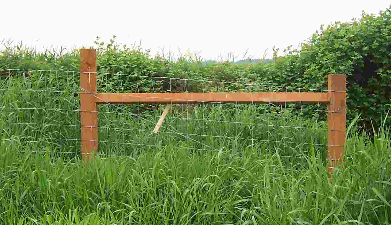
Here is how one of my H-braces turned out; I used 8’x6″x6″ treated timbers here for the posts, buried about 3′ deep; and a 8’x4″x4″ as the cross-beam, tilted slightly so water will run off it. The fence in this case is running off to the left. This brace is enduring quite a slope change; sometime maybe I’ll go back and cut off the second post a little shorter for aesthetic purposes to make it match! These seem to be holding strong, so far, under the tension of the newly-strung fence, knock on wood!

August 25, 2008 at 5:55 pm
I don’t see why you cannot purchase pre-built brace and end posts and then install on your property. I agree that it is so important and difficult to find someone to do it, if you need to have it done. Any ideas on this?
August 26, 2008 at 1:00 am
Roger, that’s a good question. I have not seen pre-built braces available in my area; but maybe they are out there. The only challenge I can see with installing them pre-built is that then you have to carefully dig the holes, like for a gate opening, to make sure they are spot-on both front-to-back and side-to-side. Hand-building your H braces, you can fudge a little bit on the side-to-side measurement, and then cut the cross-beam to fit. But, they are time consuming for sure, if there is a quicker way to make them, I’d love to know about it!
I will soon be trying out the Wedge-Loc braces on a small piece of fencing I’m going to build, I’ll report on how those go. I found a local feed store that carries them, and the owner said they work well for short sections of fencing, and that he sells a lot of them.
November 24, 2008 at 3:47 am
I would have to disagree with you. I own and operate my own fence company and have and never will build an H brace. My Grandpa ran cattle in the mountains of colorado on about 18,000 acres and he built about 250 miles of fence in his lifetime. That is comparable to 600 or 700 miles in the flatlands. I started building fence when I was 12. I am now 28, needless to say I have built hundreds of N braces. I guarantee my corners to never move for the life of the wood, and they do not.
The H brace relies on a wire to hold the fence, this does not work. There is too much pressure and stretch to stop the posts from moving. You have to get all the stretch out of the wire in order to use it for brace wire. I use old oil rig drill stems in 11 foot sections for my brace, so the weight or pull of the fence is being supported by the drill stem. There is no stretch or give in that.
The issue of too much money for a long brace or being able to secure the brace properly does not hold water. I have much better technology then my grandpa did, but the braces he built in the 50’s and 60’s are still there, and he had a ax, handsaw, and hammer. As far as the money goes my drill stem or a big 16′ pole is dollars more expensive than a short brace, but will last years longer.
I was taught how to build fence from my Dad, Uncle, and Grandpa and between the three of them they have more than 150 years of knowledge. I have hundreds of miles of fence throughout Colorado as proof that N braces work better, some built in the 40’s, some built yesterday. Feel free to visit my website at http://www.nashbrothersfence.com. By the way, I enjoyed reading your article.
November 25, 2008 at 4:38 am
Hi Clay, thanks for the comments. I usually don’t allow business advertising on my blog; but I let your comments go through because I think you have some helpful info on your website even if someone didn’t hire you to install their fence.
I am inclinded to agree with you that the N brace, the way you do it, is probably the best and most long-lasting design, especially in dryer climates. I can’t see from the photos on your site how you are attaching the diagonals to the posts, but it sounds like you notch them. I think this is the critical piece of information, is that the joint has to be really good to prevent the diagonal from slipping over time. I’ve seen very few attempts at N braces in my region, but the few I’ve seen, they tried to use nails, or very shallow notching, and I would be concerned that the diagonal would just “pop” in time.
My only comment was that I think these braces are harder for laymen to do, and also more costly, thus the reason most people choose the H instead.
I agree that the wire stretch is an issue with the H brace (though it looks like you still also use wire in your design to snug the verticals together opposite the wood diagonal?). That’s the job of the twitch, though, is to allow you to tighten it periodically if it starts to slacken. And, the wire will definitely not last as long as a wood diagonal. I considered the N brace for these reasons, but decided that in our region, where it’s SO wet, that probably the first thing to fail on the fence would be the wood posts rotting anyway. So, the cost savings and ease of installation won out for me.
I wonder, too, if fencing design doesn’t have regional styles or fads? Almost everything in my area is an H-brace, or botched attempts at H-braces. I’d be curious to see if that’s true in other parts of the country, however.
Interesting discussion, I definitely wish there was more written about this subject!
Michelle
May 17, 2009 at 2:01 am
This conversation occured a while in the past so you may have moved on to other things. But I am going to put in my vote for a modified N system. I haven’t put up a lot of fence like Clay, but I have formed an opinion.
I have goats and use a 5 wire fence to keep them in backed up with a fence charger. It works pretty good with the exeption of young kids small enough to slip under the bottom wire. And I am putting up an 8 wire deer fence for our new garden away from the house.
My corneres consist of the corner post, a brace post, a diagonal and a horizontal. I knotch them to hold and pin with 1/2 rebar pins. Compared to an H brace, it does use more wood. But a fence that falls down costs more than posts. And I don’t like using a wire for tension.
Anyway, I just got done posting about doing the corner posts for our deer fence.
-mmp
May 17, 2009 at 4:24 am
MMP, I think you have a good point-comments always welcome, because I never stop thinking about fencing and noting how others have done theirs everywhere I go! I think N braces are very strong, as long as they are properly installed and it sounds like you do them very well. I may still consider doing them that way in some spots, I’m tempted by the idea, and it might be fun to see how they perform compared to the H-braces.
It’s interesting, I’m not sure that I’ve seen any N-braces in my region (almost everybody here uses H-braces, and about half of them installed backwards!), so I wonder if it’s a regional style thing? I think too, where I am in the rainy northwest, probably the first thing to fail is the posts rotting, so I bet we never get more than 15-20 years out of a fence anyway! :-{
Michelle
June 4, 2009 at 7:46 pm
I’d love to find a source for oil rig drill stems here in the Pacific NorthWet! I wonder what a truckload would cost, or where to stop by with my trailer the next time we’re on vacation?
I started fencing here (about an hour East of Seattle) about 15 years ago using the H-post system, and am starting to see rotted posts (treated 4x4s set in concrete). Sometimes the water level here on the side of a hill is about 2″ below ground. Also the wires fail from time to time; initially I was using too small of wire.
I’m looking into concrete fence posts, especially for the end posts. While looking for concrete fence-post plans, ran across a Google book “Farm Concrete”, (c) 1917, free for download. It has a chapter on concrete fence posts, including large end-posts with ‘legs’ which would replace H-braces, plus sections on cisterns, silos, etc. etc. Well worth a read!
http://books.google.com/books?id=ikdDAAAAIAAJ&printsec=frontcover&dq=farm+concrete&ei=STcfSp7PI4KszgSwsd2uDw#PPP1,M1.
I’m thinking about line posts 5″ x 5″ at bottom, 3″ x 3″ or 3″ x 5″ at top, with ‘keyed’ replaceable(?) wood nailing strips cast in. Per the book, 1/4″ rebar seems the best reinforcement. Hopefully concrete’s gotten better since 1917, so the curing time won’t need to be as long as specified in the book. Plastic sheet on the plywood form bottom to keep moisture in, possibly a metal form instead. Not sure what to use for separators between posts when casting them. Maybe just strips of plywood or OSB, wrap it in plastic-wrap to ensure separation? Suggestions, anyone?
Best regards,
Scott
June 5, 2009 at 2:11 am
Farm Concrete- I love it! It seems you could make a lot of useful homemade things for cheap using concrete! I wonder how much tensile strength a concrete post has compared to wood? And how heavy they would be? The 6x6x8 treated posts are about all I can handle, especially when I find I drilled the hole crooked, have to do hand-digging, and lift the post in and out several times before I get it right. They are especially hard for me if they are newly treated and still soaked with moisture–oof, they are back-breaking! Thus I was slipping in some 4x6x8 posts on shorter lines; they worked ok, but a couple of them slid a bit- the extra couple of inches must make a difference in both strength and difficulty moving through the dirt!
Michelle
June 5, 2009 at 2:12 pm
i am in the process of building a small braided wire fence pasture (100′ by 50′). I have put 8′ by 4″ wood posts every twenty feet and a metal T post between every wood post. As far as corner bracing, I am unsure what to do. Are h braces the way to go for such a small pasture? If so, is there any reason i can’t use a T post as a brace post so long as i can find a way to securely attach the crossbeam? I am trying to minimize the amount of holes i have to dig for wood posts because i dig all of my holes by hand. Thanks!
-Nick
June 5, 2009 at 5:05 pm
Hi Nick
I think you do have to do some kind of corner bracing, because if you stretch the wire at all (or if animals even push on it or ever run into it) there will be tension on the corner post that will try to pull it out/over. But, for such a small run, I’m sure you can come up with something less massive than the 4×4/6×6 wood post method. I bet Wedge-Loc brackets would work for you, to make your corner braces entirely out of T-posts. I am planning on trying these for a small area I need to fence around our drainfield- I think it looks like a good invention. I have used the Wedge-Loc brackets for making little shelters, and they work pretty cool. I don’t think they are any cheaper of an option than wood, but definitely less effort and you can take them apart easily if you ever change your mind (or if you decide later you want to put in wood braces in their place). I ordered some of the Internet, but then figured out later that several farming supply stores around me carry them – I’d just never noticed them before! I asked the owner of one store, and he says he sells quite a few of them, that a lot of his clients have had success with them.
Good luck! Michelle
June 21, 2009 at 7:31 pm
[…] was going to discuss the mechanics of an H-brace, but I found a blog post that provides a good overview without being boring like I would. There are a few important rules […]
July 13, 2009 at 2:21 am
[…] year, when installing my fence H-braces, I used “twitch sticks” to tighten the diagonal wire that provides tension to the brace. Upon […]
July 29, 2009 at 1:11 pm
[…] is a very, very old fencing H-brace that I just removed from our pasture. I would venture a guess that it is part of the original farm […]
November 16, 2009 at 7:26 pm
[…] thanks to their invention; but I think this is probably a bit of an exaggeration. If there is a lot of force on the H-brace, it would easily push a T-post through the soil, much more easily than a 4×4” or 6×6” […]
April 4, 2010 at 3:51 am
I have my own ranch now and I need to redo all of my fences so I decided to see if things are done differently these days so that how I found this web sight.
I cowboyed for 3 years in North Eastern Nevada (Elko County) and the old Cowboys taught me to use H and N braces together for long stretches of barb wire fences and always used railroad ties.
Some of the old H and N braces still had the narrow gauge rail road spikes and tie plates still in the ties from the old Eureka-Palisade railroad line that ran through the ranch more then 100 years ago. The tension wire I think was the old one party phone line that serviced all the ranches way back then. Still tight and sturdy. Most of the barb wire has been replaced but lots of it is still has the old diamond shaped barbs on the wire from the late 1800’s.
Chris
April 4, 2010 at 4:35 pm
Chris, I like it! I’ve never seen an H and an N together!
Michelle
June 3, 2010 at 12:58 pm
Hi Michelle
Here is the H and N brace together holding 600′ 5 strands of barbed wire.
Thanks, Chris
June 5, 2010 at 4:03 pm
Chris, that’s a great illustration! What led you to choose a combo of an H and N brace, versus doing a double H or a double N brace? Do you think the wire on the N brace is necessary? It seems to me that since it’s strung in the same direction as the load on that brace, that initially, it will slightly counteract the intent of the N brace, but then over time, would “lose” the battle against the wood bracing and would just go slack and not add value?
Michelle
November 4, 2010 at 2:02 pm
[…] Next he used our friend’s post hole digger tractor attachment (as well as digging the holes by hand) to set the 12 foot posts for the corners, braces and gate. We got 6 inch nails to drive through to hold the cross brace and also use as a brace for the slick wire. Unfortunately, once he hung the gates, he realized that the two gate posts were a foot too far apart so he had to pull one out, dig another hole and reset it 12 inches closer. Oof! He tightened up the cross braces to get them ready to have fencing pulling on them. (I found a really great article about H braces and how they work here.) […]
January 2, 2011 at 7:28 pm
[…] The Case for the H-Brace June 2008 19 comments 5 […]
May 26, 2011 at 12:41 am
I am a boy scout working on an eagle scout project. For my project I am going to be installing a four foot tall woven wire fence at a state park in South-East Wisconsin. I found a product called quik braces that will allow me to install N braces without having to notch the posts.
I read this article and found that the ideal H brace length is 2.5 times the height of the fence. I’m wondering what is the ideal length of an N brace compared to the fence . Would it be 2.5 times the height of the fence, or would the distance between the end and brace post be 2.5 times the height of the fence? In the first case
case it appears that I will need to use the pathagorean theorem to find the distance between the posts before I mark the posts.
May 26, 2011 at 4:36 am
Hi Gage! So I think you are right, that the same rule of thumb applies, that the width of the brace should be at least 2.5 times the fence height. The same principle applies whether it’s an H- or a N-brace, that the “middle stuff” is meant to transfer some of the load horizontally onto the 2nd post; so if that “middle stuff” is more vertical than horizontal, it’s not transferring enough of the forces in the desired sideways direction. And yes again, the Pythagorean Theorem would guide you on how long to make the diagonal post. So for a four foot fence, you’re likely stuck buying a 12′ diagonal beam. You could maybe cheat and use a 10′ diagonal, it would be close to the rule of thumb and would save some money. But in theory, the wider the better for braces that need to last a long time.
I recommend not cutting the diagonal until you get the verticals up. Get your Quick Brace brackets on, then measure and mark the diagonal and cut it to fit. I have found that it’s really hard to get the vertical posts placed exactly where you planned, so it works better to cut the middle members afterwards so they fit perfectly. I checked out those Quick Brace brackets, they are pretty cool, I’ve never seen them before! Thanks for sharing and good luck with your project!
Michelle
July 3, 2011 at 2:38 am
I’ve built a number of fences doing ranch work in the summer, and your information is spot on with a good explanation of the physics. I don’t think we made out cross beam 2.5 times the height of the fence, but then we usually set our posts at 3 feet deep and tamped them well. Tamping the post right, especially the bottom half, is crucial to having solid H braces. I would not argue with Clay about N braces. His experience obviously validates their use. But I would agree with the other posts that in the Northwest the wood will probably rot and fail before the wire on a good H brace. If the diagonal wire is put on as tightly as possible before twisting it, you can get a good tight wire that will stretch very little. Doing additional tightening after the rest of the fence is built is a bit tricky, but possible.
I would add that on a very long run, we often put in a double H brace to add strength. Also, any significant rise or drop meant a double H brace at the top of the rise or the bottom of the draw and any change in fence direction, even like a 10 or 15 degree turn required a double H brace. It meant more work, but the fence would then be pulling straight against the brace posts and not sideways against the metal T posts.
I think for the average person, the H brace is easier, but for someone with lots of experience, the N brace might be a possible alternative.
October 26, 2011 at 10:31 pm
michelle
My question to you is can I use locust post and space them 12 feet a part using rough cut hemlock 2/6 for a H brace?
Gene
October 27, 2011 at 1:56 am
Gene, I don’t know very much about locust because we don’t see it sold here much, but I think I’ve heard it’s a good wood for fencing? 12 food wide for the brace is definitely good for a fence that’s 4′ high. But were you thinking of using a 2″x6″ board for the cross piece? I know I tried that once on a very short section of fence and it didn’t work well- the board is willing to bend, so it just bows under the tension between the posts. I had to compensate by putting another post underneath the middle of the cross-piece, and tying those together to make it be stiff. So I think it’s best to use a beam as the cross piece- either a 4″x4″ post, or a 4″ round post. Hope that helps!
October 30, 2011 at 8:29 pm
Michelle
Thank you for your reply I should of told you the runs I am making using the 2×6 are not more then 70 feet.I will use 4×4 now after taking to you with the longer runs. Bought wire today want to get some fencing done before the cows start freshing and the snow gets to deep. Will let you know how the 2×6 worked or I have to do it over.
Gene
November 1, 2011 at 2:39 am
Gene I think I might not be envisioning right what you are doing- are you using a 2×6 board for the “middle” part of the H brace, or for something else? Did you notice if it bowed when you put it under tension stringing the wire and tightening the diagonal wire? Let me know how it turns out!
November 18, 2011 at 7:39 pm
How did the Wedge-Loc system perform for you?
November 23, 2011 at 3:09 am
Matt, it has worked well so far- I only used them in places where there was a very short section of fence, so there isn’t a huge amount of tension on them. But they have held up for 2+ years.
November 23, 2011 at 11:16 am
Thank you for your reply. The Wedge-Loc components that I ordered from Kencove Fence Supply arrived Monday and will be installed Friday and Saturday. The area I am fencing is slightly less than 1 acre in the shape of a square so I do not believe there will be any length of fence longerthen 200 ft. or so. Many folks have had positive comments on the system but there has also been a few less than impressed in my search as well. Time will tell for me.
Thanks again.
November 23, 2011 at 5:19 pm
Matt, I’ll be interested to see how they work for you on that long of a span. Are you just using the Wedge-Loc brackets and a t-post for a diagonal, or for the whole H-brace? My guess would be t-posts for an entire H-brace won’t be strong enough for that long of a run. I would at least make sure you use as long of a t-post as you can get, and make sure the runs are perfectly straight, so there is only one direction of tension on the brace. I suspect they’ll have a tendency to twist and buckle if there is a lot of tension, and it’s not perfectly parallel to the alignment of the brace.
I’ve only used them for really tiny sections- maybe 20′ wide at the most. I have some weird fields sections with curved corners, so that’s where I’ve used them, to brace a short section between two wood H-braces. For longer runs, I’ve discovered that even 4×6″ posts tend to move in the soil more than 6×6″ posts, so I’m guessing a t-post will just “give in” to the tension completely. This may not be critical though, I think a sagging fence is mostly an aesthetic problem, not a functional one, as it still keeps in cows and sheep…
November 23, 2011 at 6:16 pm
I will be maing “N” braces as corners rather than “H” braces. I have used the “N” brace in the past with great luck using wood posts. I will be using 8′ t-posts in the corners and the literature I have suggests alternating the direction in which I wrap the wire around the corner post to prevent it from twisting the post along with starting with the bottom strand first rather than the top strand like I have done with wood posts. I will report back on the installation over the weekend.
November 24, 2011 at 1:47 pm
Michelle
After reading your thoughts on H braces,I took down the 2x6s and put in 4x4s treated with the pins through the post which I am glad I did. For if I wouldn’t have the 2x6s would have surely broke under tension.
Thank You!
November 24, 2011 at 8:55 pm
Cool, Matt, would love to hear back how they work for you, especially over time. It sure seems easier than wrestling with wood posts, if the longevity was there, I’d be into that!
January 6, 2012 at 7:57 pm
There is an excellent video available from Keystone Steel & Wire, manufacturer of Red Brand Wire Products for installing “H” Bracing. http://www.redbrand.com http://redbrand.com/InstallationVideos/Default.aspx I am a Fence Contractor located in Haymarket, VA. My primary business was residential fencing. However, I began to receive calls for Farm Fencing. I decided to investigate the different types & styles of fencing utilized in my area. There is a lot of Paddock Fencing as well as Wire fences in my area. I did my research as I wanted to make sure I was delivering a quality product that would last years. I contacted Red Brand and had lenghty discussions with Ken Edwards at Keystone. He is a wealth of knowledge and their site offers great videos for proper installation of fencing and the importance of proper bracing including “H” bracing. Just wanted to pass this information along as it has helped me become a premier Farm Fence contractor in my area. The videos are well produced and easy to follow even for a DIY.
January 7, 2012 at 4:48 am
Thanks for the tips Clyde!
July 1, 2012 at 2:44 am
I have put up several high tension 6 wire barbed wire fences and and have found the “H” System to be the best. What most people fail to understand is that you are trying to prevent the corner post from pulling up or leaning over. The “N” system tends to pull the corner post out of the ground. Just think about it. The brace acts as a lever creating an arc which will pull the corner post up in an arc. The next brace which is not a true “H” brace is with the brace at the top. Basically with the brace at the top the forces are equal on both of the two posts. Both posts will eventually lean over parallel to one another and then fail.
What I have found to work the best is a true “H” brace. The brace should be parallel with the ground about as high as you can step. About midway to the top fence wire. The “H” is tensioned together with wire across the post in a diagonal opposite the way the “N” post brace works. From the bottom of the corner post to the top of the brace post. Using the barbed wire or other high strength wire I wrap the wire around the top brace post one time and nail on. The wire is then ran to the bottom of the corner post and nailed and back to the top of the brace post. I run it around twice. The wire is then wrapped around the brace post twice and nailed and cut.
The cross wire is then tensioned. What I found works best is 1/2″ galvanized pipe (does not rust and extreme pressure can be applied.). I drill one small hole in the end for a galvanized nail. The end of the pipe is just barely put between the wires somewhere in the middle and the wires twisted. This will basically double the tension on the corner post. The brace posts acts as a lever since it is in the middle. Once tightened to maximum tension lock off the pipe against the center brace and put the nail in the pipe to hold it in place.
I have actually seen some of my brace posts bend over the years from the pressure exerted and the corner post is still straight up and down.
I never notch or drill the posts. That weakens them. The cross “H” brace post is notched in a “V” which wraps around the two main posts.
The cross brace has so much tension on it that no nails or post notches are needed.
September 3, 2012 at 4:53 pm
Dieseldan- it’s an interesting concept, putting the horizontal brace halfway down the post instead of near the top. It would definitely change the the angle of the diagonal wire, reducing the upward “lift” force on the end post. But it also seems to add a new fulcrum point in the middle of the end post, which intuitively seems undesirable to me- that it creates a new lever action that encourages the post to pull out of the ground again? I’m not sure what the net effect of the two changes together would be to the overall design, I think someone would have to do the math to figure it out for sure.
I think the biggest key with any of these braces is the width dimension- if people make an H or N brace too narrow, then the diagonal wire/brace will be putting too much upward force on the end post, encouraging it to pull out of the ground. The wider the whole brace is, the more that diagonal angle is flattened, thus reducing the upward force.
Probably soil type and whether or not concrete is used as a footing on the post impacts the need for a wider H brace. We have pretty dense, mucky soils here, and often rocky as well. So I think people in our region get by with a lot of mistakes in brace design, and the soil still holds the post and doesn’t allow it to pull out. But I’m imagining that people in places with dry, sandy soil need to worry more about the post migrating upward as it leans. Then it would be critical to make sure the brace is as wide as possible.
September 3, 2012 at 6:21 pm
To get around the point of the horizontal being to low or to high this is what the old cowboys taught me.
On making H braces I always make the vertical post 2 1/2 times wider then the height of the horizontal post. example: If the horizontal post is going to be 4′ off the ground I space the vertical post 10′ or more.
My H-braces are made of Railroad ties with the vertical being 5″-6″ round pressure treated post. When I was making a living as a Cowboy in NE Nevada 12 years ago, the ranch still had H-braces made out of the narrow gage railroad ties that ran through the ranch 100+ years ago. Some of the H-braces still has the narrow gage tie plates and spike still on them.
September 20, 2012 at 5:19 am
Using high tensile wire for your diagonals when constructing H braces will eliminate the possibility of stretching if your fence corners are far out in the field and not in an area that can be periodically adjusted. Otherwise, like most things, fences need maintenance and H braces which are properly constructed and maintained can be self installed without you having to be professional fence builder who does this every day.
October 19, 2012 at 10:14 am
very nice look of fences…
thanks for sharing…
October 19, 2012 at 3:03 pm
Thanks Harris!
November 18, 2012 at 6:43 am
Updates on the WedgeLocs? I have a bag full, waiting to be implemented. One set for dog yard, and one set for a 152′ run of ‘horse fence’. Anxious!!
November 18, 2012 at 7:24 pm
Jen, I like them fine, the braces I’ve made out of them are still standing straight 3+ years later. I had made a shelter out of them and t-posts too, and that actually did fall prey to a weakness- somebody dinged one of the posts with a mower. The shelter cannot handle any twisting kinds of forces like that, so it torqued it and made it fall down. Which wouldn’t happen with a wood post structure so easily. But I do think they are fine for braces.
April 13, 2013 at 3:26 pm
I prefer the H over the N brace. The N is harder to build correctly. People tend to cut the N braces notches too deep. The N brace tension wire then serves to break the 2nd post in the brace just above the ground. Additionally, securing N Brace the diagonal brace posts is harder than the H Brace. If the N brace moves, the diagonal will jack the end post out of the ground.
April 13, 2013 at 5:25 pm
Rob, I agree, I think this is one reason why the H brace is the most popular, it’s just more straightforward to construct.
April 17, 2013 at 8:16 am
Hi Michelle,
Thanks for your informative page, it has certainly made my fencing alot easier. Here is a question for you. What do you do when applying the H brace where the corner and brace post are not level, as the fenceline runs up or down a hill? To get the crossmember level on some of these H braces I need to build, will mean it reaches the corner and brace posts at different heights. What are your thoughts here on what is more critical – getting the crossmember level, or making sure it attaches to the corner and brace posts at the same height?
Thanks Bryan
May 13, 2013 at 2:51 am
Bryan, that is an interesting question, I had to think about it for a while. I think, when you think about the forces of the fence pulling on the brace, the pull is going to be parallel with the ground. So, conceivably, you could make the cross-member also parallel with the ground, though that makes for some tricky angle cuts which may not be convenient to do in a field. I think it would also be OK to make the cross-member level (to the world), knowing that it’ll be set low on whichever post is downhill from the other.
When you think about a brace- say the case where the corner is on the top of a hill-the fence is going to be pulling it at an angle, which can be split into a horizontal force, and a downward force. So the horizontal pull is less than if the fence is not on a hill, and the H brace isn’t under as much strain, nor is the corner post as tempted to “flip” since the fencing is also pulling it downward. So it’s probably ok if the horizontal piece is lower on the corner post, as it doesn’t need to transfer as much load from the top as a straight fence does.
In the case where the corner as at the bottom of a hill, the fence will pull at an angle which can be split into a horizontal force, and an upward force. Here I think it’s also ok to have the horizontal hit a lower portion of the 2nd post of the brace, because there is less horizontal pull, and not that much load on the 2nd post. The interesting thing about this scenario is that the corner post has two forces pulling it upward: the fence itself, and also the diagonal wire coming from the 2nd post. So, depending on how steep the hillside is, it may be worth doing something extra to discourage the corner post from popping out of the ground- like a good concrete footing, or a flared post that’s wider at the bottom.
August 23, 2014 at 6:16 am
Thank you for sharing your thoughts on fencing. I live in Norway an am about to install an electric high tensile fence. The ground is rolling and rocky thus making bracing difficult. I wonder if you have any experince with or toughts on anchoring. Generally I do not see much information on anchoring the posts. Products like gripple ground anchor look easy to use and I think it sounds smart to string a wire from the top of a corner post to a ground anchor.
Karsten
August 23, 2014 at 2:53 pm
Karsten I don’t know much about those, but I recall reading about this scenario, so I think others have found solutions to this. IKencove fencing supply in the US has a lot of articles and solutions. I couldn’t find one on their various “earth anchor” products, but maybe you could email them and ask, or do a little more searching on that topic. I think in a way, once you get something successfully driven into the soil, the rockiness is a help, as it really deters movement, compared to soft soils. So the effort may be greater to install, but I bet it lasts a long time!
February 23, 2015 at 10:31 pm
Has any one ever heard of a flat rock support that a old feller told me years ago that they used a lot in the south west or sandy places, lets say its a 8 foor end post and you notch it say about 6 inches below the top , and then take lets say another 8 foot by say 4 inch and fix it so that it fits into the notch you made on the end post, and put a flat rock on the ground so that the other end of the 4 inch post lays on the flat rock, then you takle some high tensil wire or # 9 wire and wrap it around both post about 6 inches off the ground, and then after you tie the wires together , you twist them until they are tight, and as the fence sages, if it does you can twist the wire and by doing this, the post on the flat rock will slide on the rock as you twist the wires and push against the top of the end post, hope this is clear enough? Have a good day all, I just thought this was very impressive when the old feller told me about this.
March 1, 2015 at 4:26 pm
James, yes, I have seen this type of brace described somewhere too. I searched for a diagram of one, and found one here:
http://www.farmshow.com/a_article.php?aid=4494
I’m trying to think if there are any downsides to it, it seems like it uses the same principles of physics and should work just as well. The drawbacks might be that the diagonal post needs to be long, so more expensive. And I think you’d have to make sure that the diagonal was in line with the pull of the fence. If it slips off to the side, it may fail. So I wonder if it would be worth adding something to make a “channel” so that the rock “slider” is constrained to only slide in the direction of the fence? Other than that, it seems like if you make them correctly, they should work. I wonder why this design hasn’t caught on more? Maybe just convention, everyone just does what seems to work for their neighbor…
May 16, 2015 at 5:56 pm
Thank you for explaining WHY the diagonal wire goes bottom to to top, and which way is correct. I have searched and searched. Yours is the only good explanation I have ever found. I am hangin 12 gates, and now know HOW to properly accomplish the bracing. Again, well done and thanks.
Fred from Oregon
May 17, 2015 at 6:00 am
Glad it was helpful Fred!
August 5, 2016 at 2:01 am
[…] Comparison of bracing techniques – Collie Farm blog, Rural Fence Post Bracing. […]
January 2, 2017 at 2:32 pm
I have been in a debate about how to use a H brace. Does the wire attache to the H brace on both posts and is stretched in opposite directions in a manner that the wire is pulling against the other one?
January 2, 2017 at 4:26 pm
Hi Edward, I’m not sure I understand what you are describing. The way I’ve done it, the wire is made into one continuous loop, that loops around both posts. Staple to the outside/top of one post, and the outside/bottom of the other post, to keep it from sliding vertically. Then it is tightened, so that it’s under tension. Either with a “twitch” type stick in the middle that you can twist; or with a ratchet-style tensioner. This way, as the end post wants to try to “flip” out of the ground, yielding to the tension of the long fenceline, the bottom of that post is pulling against the H-brace wire, which is pulling at the top of the 2nd post in. But the top of that post is pushing back through the horizontal beam, balancing out the tensions and encouraging that end post to stay in place.
I’ve seen some people not use a loop, but rather staple a single strand to the outside of the posts. I don’t think this is as good, as it’ll probably encourage the posts to twist and get misaligned over time. It’s best to keep the lines of tension as straight in line with the whole fenceline as possible.
September 13, 2017 at 12:52 pm
Is it possible to build an H brace that’s shorter and not as wide as the prior section? I’m building a short grape trellis (~15ft x 2 sections) and I’d like the end braces to not take up so much space. The tension on the trellis could still be significant. I see pictures all over the internet of trellises built without any real end bracing (or a single brace wire) and I feel that this just wont hold up in the long run, especially with vertical weight on the wire. Could I have a 5 ft high trellis, with a 2ft high h-brace on each end?
I think I might still have to run the h-brace wire from the top of the last post, around both sides of the horizontal post (to eliminate any outward force) and to the bottom of the bracing post, so that the lever is still as complete is possible.
Is there any way to build a structurally solid end brace that doesn’t take up as much space on either end of the trellis?
November 2, 2018 at 4:59 am
Dan, I think for trellises, yeah, you could but shorten the height and width and probably still get what you wanted. Though the weight of grapes and the tension between the end posts is still a force, it’s not as great of a force as 1,000 feet of woven wire fencing all pulling against one end post. My husband braces his grape trellises with one extra T-Post, sometimes kind of angled-in away from the pulling force, and with one wire running from the main run diagonally down to the brace post. He puts a tensioner between them so he can ratchet it down, and this works pretty well, and doesn’t consume a lot of space. Worst case, things start leaning over time, and you have to put in something stronger, but that’s easy to do in a garden. Hope that helps!
October 27, 2019 at 2:13 pm
Thanks for the very detailed explanation of the benefits and pitfalls of corner bracing ,super helpful!
I’m planning to use an N-brace for aesthetic reasons, and from past trials and errors I’ve noted the problem that you describe – that there is a chance the corner post will “pivot” around the brace point and lift itself up if the diagonal brace is not placed correctly.
However, I’m not entirely sure that it’s a too narrow angle between the diagonal brace and the corner post that is the problem. From my observations it seems that it’s most commonly a too low contact point between the corner pole and the diagonal brace that’s causing a kind of “lever” effect, where force on the top part of the corner post is turned into rotation around the brace through a kind of “lever effect”?
I’m no engineer, so not sure if my reasoning is correct. What are your thoughts on the placement vs. the angle of the N brace? Would a small angle (< 45 degrees) but high brace point (near the top of the corner post) work? Equally, would a large angle and a low brace point work as well?
October 27, 2019 at 4:51 pm
Magnus, I think you are right, and it is related to the problem of too narrow of a brace, but not quite the same problem. With the N brace, if the diagonal pole is attached to the corner post midway along its height, rather than near the top, those upward forces pushed back on the corner post can make it wan’t to cantilever over and past the diagonal over time. I could imagine that in an attempt to save lumber costs and avoid having a very long diagonal, folks could be tempted to use a shorter board and attach it midway on the heights of both posts, and this would be more prone to failure.
May 3, 2020 at 5:30 pm
Thanks for this post. I was looking for information about making corners and ends for a welded wire fence.
I know that this blog post is very old, but I see that you responded in 2019, so hopefully you are being notified when a new post is made here.
My use case is probably different than most here in that I don’t think that I need to have the wire under as much tension as would usually be required for a fence. My back yard is already enclosed by chain link fence. My girlfriend would like to have a fence inside the back yard to keep two small dogs (20 pounds) away from a wooded area in the back yard. We tried a fabric mesh fence, but animals (rabbits, etc) keep eating holes through the fence.
Even though it is overkill, she wants a 4 foot high fence. In all there are three runs of this fence of 30 feet each, with one corner, and one gate, so four ends and one corner. The fence does not have to be stretched very tightly, but I’m sure that even so we need to do something to assist the corners. I don’t want to use wood for the corners unless I have to. We are trying to do everything as inexpensively as possible, consistent with something that will hold up over the years. Honestly, it won’t bother us too much if the corner and ends bend in a bit over time, as long as the fence is still functional. Our plan is to use welded wire and T-posts.
I have two ideas for how to tackle this.
The first option is that I have some top rail from an old chain link fence. I thought that maybe I could run the top rail at the top of the fence and use something like U-bolts to attach it to the T-posts. I’m thinking that if the top rail carries some of the tension then I could stretch the wire some without needing corner bracing. I realize that for this to be successful, the top rail will need to be secured at the top of each post, and perhaps tied to the wire along the way as well, to prevent the tendency of the top rail to bow.
The other option that I considered would be to make an N or H brace at each end and the corner. For an H brace, I would use a T-post as the horizontal member, and for an N brace, I would use a T-post as the diagonal member. I’d hope to be able to attach that with U Bolts as well, although I could use wedge locs as well if I needed to . The reason for not using them initially is that using them would probably double the cost of this installation.
I realize that using U bolts sounds amateurish, but my goal is just to be able to have more tension on the wire than I could get if I didn’t do something.
What do you think of this, or do you have any other suggestions.
May 9, 2020 at 4:51 am
I referred to this blog and did a lot of research when I built my fence in 2012. I had never built a fence before and there is only one thing I would do different if I were to build another fence today. The fence has been rock solid and I used H braces made of 6″ round pressure treated posts. I understand you don’t want to use wood so no need to go into details about what I did there. I also decided to use horse fence instead of welded wire because about 200ft of welded wire existed and it didn’t seem to fare well over time. The horse fence is strong and easy to find in 4 and 6 ft heights. I used H braces for ends and corners and the corners can be made at any angle. Horse fence DOES need to be stretched or it will be loose and look terrible but it’s easy to do. I made a stretcher out of 3 2×6’s that bolt together over the end of the fence and sandwich it. for 6 ft fence the boards are 3-4 ft long with a strong wire or chain loop from the top and bottom bolts to a come along. Stretching was easy and then I fastened to t post while under tension. I did about 1200ft of this fence.
Now… this is what I would have done differently. I would have dug a trench, 1-2 ft deep and buried the bottom portion of the fence. A trencher works nicely for this. So 6ft fencing becomes 4-5 ft high. Critters are constantly digging under the fence, especially skunks that dig holes everywhere. I have to check thwe fence regularly and fill holes constantly. Some holes are big enough for the dogs to get under. ALSO, I would have put chicken wire fencing all along the the bottom of the fence which has smaller holes than the horse fence. Rabbits, ground squirrels, and entire families of quail walk right through the horse fence and constantly tease the dogs to chase them right to the fence line.
June 3, 2020 at 4:36 am
Hi Scott,
Thanks for the tips.
Since you didn’t bury the fence, I’ve read that laying a one or two foot piece of welded wire on the ground adjacent to the fence will stop animals from digging under it as well. Clearly there are some case where that is not practical and some cases where it is.
We are planning on trenching the wire in about 4″ underground by hand, but after what you said, I am thinking about if we need to do it deeper. than that.
June 21, 2020 at 6:58 pm
ItsMeToo- I get it when you just want something cost-effective and quick that will work for “right now” and probably almost anything will. There is a product called Wedge-Loc that I have written about elsewhere that allows you to connect together T-posts to make braces etc. I have used them before and they do work. But they are prone to failure over time, just because if the pulling forces are putting any torque on them, over a few years, they will slip, and the brace will fall apart. Not to say that you couldn’t just re-set it if that happens.
I think you are also right in that if it’s a short fence with small dogs, it doesn’t need to be under a lot of tension. Probably the drawback is, if the dogs jump on it when they bark at “things”, over time, they will cause it to bow and sag and it may look unsightly. It’s also maybe a slightly higher risk of them getting a foot caught in it or something. Vs a well-tensioned fence has a lot of “spring” so if an animal smacks into it, it yields but bounces them, and it leaves fewer slack places where, e.g. a toe can get caught.